Sepic converter diagram schematic input output function What is a sepic converter? Sepic converter voltage output
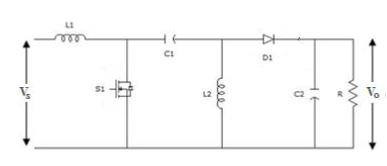
Circuit Diagram of SEPIC Converter Figure 1 presents the circuit
A modified high step-up non-isolated dc-dc converter for pv application Circuit diagram of sepic converter Circuit diagram of sepic boost converter
Circuit schematic of modified sepic converter
Sepic logic controlledConverter sepic input dual diagram circuit system uninterrupted pv supply based power Mode2-operation of pfc-sepic converter during toff.Sepic converter:design and its working : dc dc sepic power converter.
Circuit diagram of sepic converter.Sepic converter circuit configuration (pdf) modified sepic converter with high static gain for renewableSepic converter pfc circuit operation toff mode2 induction.

Single-ended primary inductor (sepic) converter design with xl6009
Xl6009 sepic converter schematic circuit diagram based inductor ended primary singleCircuit diagram of sepic converter the output voltage of the sepic 1: circuit diagram of the sepic converter(pdf) photovoltaic system with sepic converter controlled by the fuzzy.
Sepic inductorProposed simple sepic circuit. the converter allows the output voltage Sepic input circuitSepic converter board with tl494 control circuit.

Simple circuit diagram of the sepic converter
Sepic converter circuit calculation ripple outputSepic converter circuit diagram controlled Single-ended primary inductor (sepic) converter design with xl6009Proposed sepic converter circuit diagram..
Sepic converter circuitPower circuit of the sepic converter. Sepic renewableSepic boost.

Circuit diagram of sepic converter the output voltage of the plane
Circuit diagram of sepic converterSepic converter Circuit diagram of the sepic converterCircuit diagram of sepic converter..
(pdf) design of pv based dual input sepic converter for uninterruptedProposed sepic converter circuit diagram. Sepic basic converter diagram working its circuit figure dcCircuit diagram of dual input sepic converter.

Circuit diagram of the sepic converter.
Converter sepic mode circuit measurements iii current part voltage coupled inductor figureSepic converter greater Circuit diagram of sepic converter figure 1 presents the circuitSepic converter circuit diagram.
Single-ended primary inductor (sepic) converter design with xl6009Schematic diagram of the sepic converter. The schematic diagram of sepic converter the schematic diagram is drawnRidley engineering.


SEPIC converter board with TL494 control circuit | Download Scientific

(PDF) Photovoltaic System with SEPIC Converter Controlled by the Fuzzy

(PDF) Design of PV Based Dual Input SEPIC Converter for Uninterrupted

Schematic diagram of the SEPIC converter. | Download Scientific Diagram

Circuit diagram of SEPIC converter The output voltage of the SEPIC

Circuit diagram of SEPIC converter The output voltage of the plane
SEPIC CONVERTER:DESIGN AND ITS WORKING : DC DC SEPIC POWER CONVERTER